miniBOOSTER
Hydraulic Pressure Intensifiers covering 13 intensification factors up to 5,000 bar
and flows up to 400 l/min, using almost any media including tap water. In fact, the range
encompasses flanged versions, tube versions and cartridge versions and standard
blocks with built-in valves option that dramatically REDUCES the need for space and piping.
MINIMUM SIZE - MAXIMUM POWER
![]()
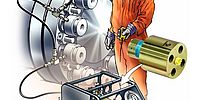
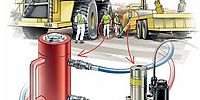
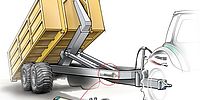
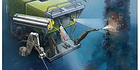
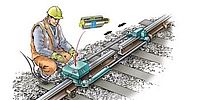
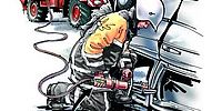
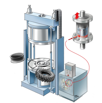
Applications
What is a miniBOOSTER?
miniBOOSTERs are pressure intensifiers changing back and forth
that engineers can mount on low-pressure hydraulic systems. The task of
a miniBOOSTER is to immediatelly intensify system pressure providing it
with a higher outlet pressure. The miniBOOSTERs come in a vast range
of models, each representing different functions for different environments.
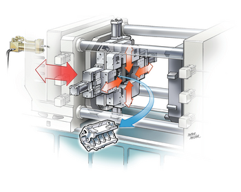
How does miniBOOSTER work?
a High-performance boost
miniBOOSTERs are oscillating boosters. They automatically intensify system pressure giving a higher outlet pressure and will compensate for oil loss on the high-pressure side. This function of the miniBOOSTER is based on the patented system as shown in the animation on the left side.
The basic design incorporates a low-pressure piston (LP), a high-pressure piston (HP), and a bistable reversing valve (BV1). The dump valve (DV) is an optional feature.
Detailed description
Hydraulic fluid at system pressure is supplied to port IN. It flows freely through check valves KV1, KV2 and DV (if included) via port H. Now all flow goes through the booster, and a cylinder on the high pressure side H will move forward at high speed. As the cylinder meets resistance pressure increases in the high-pressure side H equal to the pump supply pressure. This causes check valves KV1 and DV to close and the oil directs to Vol 1. The bistable valve BV1 connects Vol 2 to the tank via Vol 3. As pump pressure is applied to Vol 1 the pistons move downwards.
When the piston has fully moved down, Pilot Supply 1 energizes by operating the bistable valve BV1 changing its position. Fluid lleds to Vol 2 moving the pistons upward delivering fluid at higher pressure. The resultant pressure is determined by the ratio in area of the low pressure piston LP to the high-pressure piston (HP).
What is the outcome?
At the point when the high-pressure piston (HP) has moved up, Pilot Supply 1 connects to the tank, the bistable valve BV1 returns to its initial position, and the cycle repeats until the required end pressure builds up. Afterwards, the intensifier stops and will only start again to maintain the pressure at the high pressure side of H.
Pressure can be relieved from the high-pressure side through the pilot-operated check valve DV (if included). By connecting port R to the supply pressure and port IN to the tank, Pilot Supply 3 will be pressurised, allowing the fluid from the high-pressure side H to flow back to the tank.